

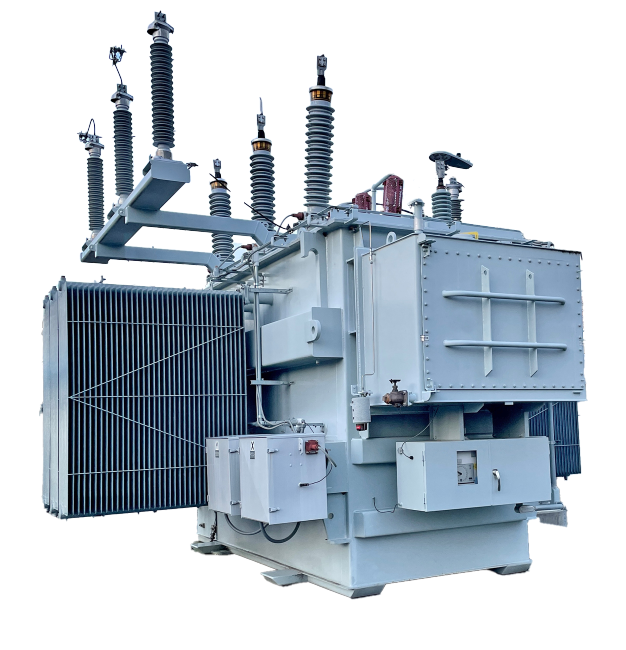
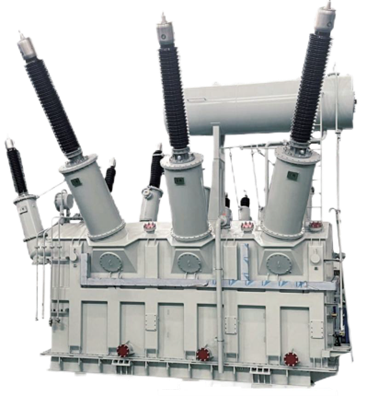
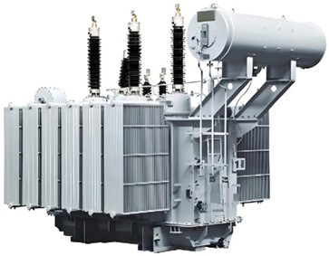
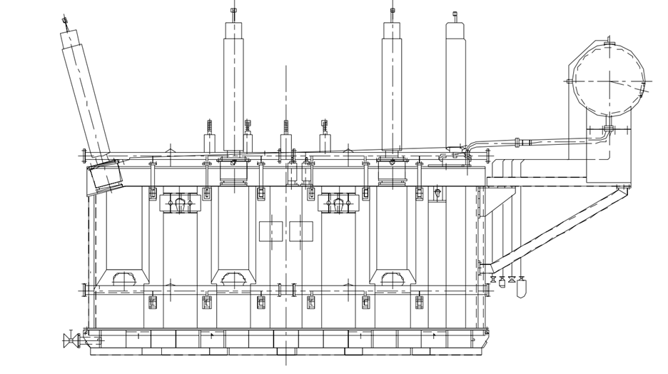
An Electrical Substation Transformer is a core component of the American power grid that reliably converts electrical voltage levels between generation, transmission, and distribution systems. Designed to handle high-capacity loads, these transformers either step up voltages for long-distance transmission or step down voltages for safe distribution to homes, industries, and commercial facilities across the USA.
They operate on electromagnetic induction principles, using primary and secondary windings around a magnetic core to efficiently change voltage levels while minimizing energy loss. High-quality substation transformers are essential for reducing transmission losses, ensuring grid stability, and supporting decades of continuous operation under varying load conditions.
In modern U.S. infrastructure, advanced transformer technologies help utilities meet stringent ANSI/IEEE performance and safety standards, accommodate renewable energy integration, and support rapid demand growth from data centers and EV networks.
|
KVA Ratings |
500, 1000, 1500, 2000, 2500, 5000 and higher |
|
No. of Phases |
Three-Phase |
|
Frequency |
50 Hz – 60 Hz |
|
Primary Voltage |
Up to 230 kV |
|
Secondary Voltage |
120 V – 69 kV |
|
Tapping Range |
±5% or ±10% |
|
Winding Material |
Copper, Aluminum |
|
Cooling Type |
ONAN, ONAF |
|
Fluid Type |
Non-PCB Mineral Oil or FR3 Fluid |
|
Connection Type |
Delta-Wye |
|
Mounting |
Stationary Substation Installation |
| Transformer Testing (ANSI C57.12.90) | |
|---|---|
|
All substation transformers undergo the following standard commercial tests: |
|
|
No-Load Losses |
Evaluated at rated voltage |
|
Load Losses |
Measured under rated conditions |
|
Percent Impedance |
Calculated at rated current |
|
Excitation Current Test |
Conducted at 100% voltage |
|
Ratio Tests |
Ensured across all tap settings |
|
Polarity and Phase Relation Tests |
Verifies orientation |
|
Induced Potential Tests |
Simulates electrical stress scenarios |
|
Impulse Tests |
Full wave and reduced wave performance tested |
| Standards and Certifications | |
|---|---|
|
Sound Level |
Designed to meet NEMA Noise Standards |
|
IEEE Compliance |
Conforms to IEEE C57.12.10 Standards |
|
UL Certification |
UL Listed and Compliant |
|
Efficiency |
Meets DOE 2016 Efficiency Standards or higher |
|
Temperature Rise Options |
55°C, 65°C, 65/75°C |
| Primary Protection Devices | |
|---|---|
|
Internal Fuses |
Current-limiting types for overcurrent protection |
|
External Surge Arresters |
Available for high-voltage applications |
| Tank and Material Specifications | |
|---|---|
|
Tank Material |
Mild Steel or Stainless Steel with advanced coating systems |
|
Tank Coating System |
Complies with IEEE Std C57.12.28 for durability |
|
Enclosure Type |
Weather-resistant construction suitable for outdoor substation environments |
| Quality Control and Warranty | |
|---|---|
|
Quality System |
ISO 9001 Certified |
|
Routine Tests |
Conducted per ANSI® and IEEE® standards |
|
Warranty |
Industry-standard coverage for defects and performance |
| Rated Capacity (kVA) | High Voltage (kV) | Tapping Range | Low Voltage (kV) | Vector Group | No-load Loss (%) | Impedance Voltage (%) | No-load Losses (kW) | On-load Losses (kW) |
|---|---|---|---|---|---|---|---|---|
|
6300 |
110, 112 |
±2×2.5% |
6.3, 6.6, 10.5, 11 |
YNd11 |
0.77 |
630 |
9.3 |
36 |
|
8000 |
110, 112 |
±2×2.5% |
6.3, 6.6, 10.5, 11 |
YNd11 |
0.77 |
910 |
11.2 |
45 |
|
10000 |
110, 112 |
±2×2.5% |
6.3, 6.6, 10.5, 11 |
YNd11 |
0.72 |
1310 |
13.2 |
53 |
|
12500 |
110, 112 |
±2×2.5% |
6.3, 6.6, 10.5, 11 |
YNd11 |
0.72 |
1580 |
15.6 |
63 |
|
16000 |
110, 112 |
±2×2.5% |
6.3, 6.6, 10.5, 11 |
YNd11 |
0.67 |
1890 |
18.8 |
77 |
|
20000 |
110, 112 |
±2×2.5% |
6.3, 6.6, 10.5, 11 |
YNd11 |
0.67 |
2310 |
22.0 |
93 |
|
25000 |
110, 112 |
±2×2.5% |
6.3, 6.6, 10.5, 11 |
YNd11 |
0.62 |
2730 |
26.0 |
110 |
|
31500 |
110, 112 |
±2×2.5% |
6.3, 6.6, 10.5, 11 |
YNd11 |
0.60 |
3200 |
30.8 |
133 |
|
40000 |
110, 112 |
±2×2.5% |
6.3, 6.6, 10.5, 11 |
YNd11 |
0.56 |
3830 |
36.8 |
156 |
|
50000 |
110, 112 |
±2×2.5% |
6.3, 6.6, 10.5, 11 |
YNd11 |
0.52 |
4540 |
44.0 |
194 |
|
63000 |
110, 112 |
±2×2.5% |
6.3, 6.6, 10.5, 11 |
YNd11 |
0.48 |
5410 |
52.0 |
234 |
|
75000 |
110, 112 |
±2×2.5% |
6.3, 6.6, 10.5, 11 |
YNd11 |
0.42 |
6200 |
59.0 |
278 |
|
90000 |
110, 112 |
±2×2.5% |
6.3, 6.6, 10.5, 11 |
YNd11 |
0.38 |
7500 |
68.0 |
320 |
|
120000 |
110, 112 |
±2×2.5% |
6.3, 6.6, 10.5, 11 |
YNd11 |
0.34 |
10300 |
84.8 |
397 |
| Rated Capacity (kVA) | High Voltage (kV) | Tapping Range | Low Voltage (kV) | Vector Group | No-load Current (%) | Impedance Voltage (%) - Step Up | Impedance Voltage (%) - Step Down | No-load Losses (kW) | On-load Losses (kW) |
|---|---|---|---|---|---|---|---|---|---|
|
6300 |
110±2×2.5%, 121±2×2.5% |
35, 38.5 |
6.3, 6.6 / 10.5, 11 |
Yyn0d11 |
0.82 |
HV–MV: 17.5–18.5HV–LV: 17.5–18.5MV–LV: 6.5 |
HV–MV: 10.5HV–LV: 17.5–18.5MV–LV: 6.5 |
11.2 |
47.0 |
|
8000 |
110±2×2.5%, 121±2×2.5% |
35, 38.5 |
6.3, 6.6 / 10.5, 11 |
Yyn0d11 |
0.78 |
HV–MV: 17.5–18.5HV–LV: 17.5–18.5MV–LV: 6.5 |
HV–MV: 10.5HV–LV: 17.5–18.5MV–LV: 6.5 |
13.2 |
56.0 |
|
10000 |
110±2×2.5%, 121±2×2.5% |
35, 38.5 |
6.3, 6.6 / 10.5, 11 |
Yyn0d11 |
0.74 |
HV–MV: 17.5–18.5HV–LV: 17.5–18.5MV–LV: 6.5 |
HV–MV: 10.5HV–LV: 17.5–18.5MV–LV: 6.5 |
15.8 |
66.0 |
|
12500 |
110±2×2.5%, 121±2×2.5% |
35, 38.5 |
6.3, 6.6 / 10.5, 11 |
Yyn0d11 |
0.70 |
HV–MV: 17.5–18.5HV–LV: 17.5–18.5MV–LV: 6.5 |
HV–MV: 10.5HV–LV: 17.5–18.5MV–LV: 6.5 |
18.4 |
78.0 |
|
16000 |
110±2×2.5%, 121±2×2.5% |
35, 38.5 |
6.3, 6.6 / 10.5, 11 |
Yyn0d11 |
0.68 |
HV–MV: 17.5–18.5HV–LV: 17.5–18.5MV–LV: 6.5 |
HV–MV: 10.5HV–LV: 17.5–18.5MV–LV: 6.5 |
22.4 |
94.0 |
|
20000 |
110±2×2.5%, 121±2×2.5% |
35, 38.5 |
6.3, 6.6 / 10.5, 11 |
Yyn0d11 |
0.65 |
HV–MV: 17.5–18.5HV–LV: 17.5–18.5MV–LV: 6.5 |
HV–MV: 10.5HV–LV: 17.5–18.5MV–LV: 6.5 |
26.4 |
112.0 |
|
25000 |
110±2×2.5%, 121±2×2.5% |
35, 38.5 |
6.3, 6.6 / 10.5, 11 |
Yyn0d11 |
0.60 |
HV–MV: 17.5–18.5HV–LV: 17.5–18.5MV–LV: 6.5 |
HV–MV: 10.5HV–LV: 17.5–18.5MV–LV: 6.5 |
30.8 |
133.0 |
|
31500 |
110±2×2.5%, 121±2×2.5% |
35, 38.5 |
6.3, 6.6 / 10.5, 11 |
Yyn0d11 |
0.58 |
HV–MV: 17.5–18.5HV–LV: 17.5–18.5MV–LV: 6.5 |
HV–MV: 10.5HV–LV: 17.5–18.5MV–LV: 6.5 |
36.8 |
157.0 |
|
40000 |
110±2×2.5%, 121±2×2.5% |
35, 38.5 |
6.3, 6.6 / 10.5, 11 |
Yyn0d11 |
0.56 |
HV–MV: 17.5–18.5HV–LV: 17.5–18.5MV–LV: 6.5 |
HV–MV: 10.5HV–LV: 17.5–18.5MV–LV: 6.5 |
43.6 |
189.0 |
|
50000 |
110±2×2.5%, 121±2×2.5% |
35, 38.5 |
6.3, 6.6 / 10.5, 11 |
Yyn0d11 |
0.55 |
HV–MV: 17.5–18.5HV–LV: 17.5–18.5MV–LV: 6.5 |
HV–MV: 10.5HV–LV: 17.5–18.5MV–LV: 6.5 |
52.0 |
225.0 |
|
63000 |
110±2×2.5%, 121±2×2.5% |
35, 38.5 |
6.3, 6.6 / 10.5, 11 |
Yyn0d11 |
0.55 |
HV–MV: 17.5–18.5HV–LV: 17.5–18.5MV–LV: 6.5 |
HV–MV: 10.5HV–LV: 17.5–18.5MV–LV: 6.5 |
61.6 |
270.0 |
|
75000 |
110±2×2.5%, 121±2×2.5% |
35, 38.5 |
6.3, 6.6 / 10.5, 11 |
Yyn0d11 |
0.50 |
HV–MV: 17.5–18.5HV–LV: 17.5–18.5MV–LV: 6.5 |
HV–MV: 10.5HV–LV: 17.5–18.5MV–LV: 6.5 |
70.2 |
307.7 |
|
80000 |
110±2×2.5%, 121±2×2.5% |
35, 38.5 |
6.3, 6.6 / 10.5, 11 |
Yyn0d11 |
0.50 |
HV–MV: 17.5–18.5HV–LV: 17.5–18.5MV–LV: 6.5 |
HV–MV: 10.5HV–LV: 17.5–18.5MV–LV: 6.5 |
73.7 |
323.0 |
|
120000 |
110±2×2.5%, 121±2×2.5% |
35, 38.5 |
6.3, 6.6 / 10.5, 11 |
Yyn0d11 |
0.50 |
HV–MV: 17.5–18.5HV–LV: 17.5–18.5MV–LV: 6.5 |
HV–MV: 10.5HV–LV: 17.5–18.5MV–LV: 6.5 |
87.1 |
381.8 |
| Category | Recommended Technical Fields |
|---|---|
|
Electrical Ratings |
HV/rectifier side voltage, MVA rating, phase configuration, connection group |
|
DC Output Spec |
Secondary voltage, max DC current (e.g., 44,000 A), number of pulse (6/12-pulse) |
|
Short Circuit Design |
Dynamic forces, bracing, %Z (typ. 7–9%), short-circuit duration withstand |
|
Cooling |
ONAN/ODAF with overload profile, forced oil flow control |
|
Losses & Overload |
Total losses, overload curves (15 min, 30 min), transient thermal limits |
|
Tap-Changer |
Off-load or on-load tapper, especially for arc voltage regulation |
|
Testing |
Impulse withstand, thermal cycle, core hot spot monitoring |
|
Accessories |
Current transformers, temperature alarms, explosion vent |
| Category | Recommended Technical Fields |
|---|---|
|
Voltage Ratings |
Nominal voltage, phase (1Φ/3Φ), insulation class |
|
MVAr Capacity |
Rated reactive power, core/reactor type (gapped core, air-core, iron-core) |
|
Impedance & Inductance |
Nominal inductance, total loss (core + stray), Q factor |
|
Losses |
No-load loss < 0.5%, stray losses, load factor impact |
|
Cooling |
Natural air (dry), ONAN, ONAF |
|
Noise Level |
≤ 65–75 dBA |
|
Impulse Ratings |
LIWL, PF withstands |
|
Mounting |
Skid type or platform-based |
|
Testing |
Magnetic balance, induced voltage, high voltage withstand |
Efficient Voltage Conversion – Substation transformers step up generator output for long-distance transmission and step it down for safe distribution, ensuring electricity reaches homes and industries efficiently. This minimizes energy loss over transmission lines, improving overall grid performance.
Reduced Transmission Losses – By increasing voltage for transmission and lowering current, transformers significantly cut power losses (I²R losses) during long-distance electricity transfer, which is essential in high-capacity systems such as MW-level networks. – By increasing voltage for transmission and lowering current, transformers significantly cut power losses (I²R losses) during long-distance electricity transfer, which is essential in high-capacity systems such as MW-level networks.
Stable Voltage & Power Quality – These transformers help regulate voltage levels, reducing fluctuations that can harm equipment or disrupt operations and enhancing the reliability of the U.S. power grid.
Improved System Resilience – Substation transformers isolate sections of the grid, helping prevent faults from cascading and contributing to quicker recovery during disturbances or overloads.
Cost Efficiency – High-efficiency transformer designs (up to ~98% or more) reduce energy waste, lowering operational costs and improving total cost of ownership for utilities and large consumers.
Supports Renewable Integration – Modern transformers help integrate renewable energy sources by managing variable outputs and ensuring compatibility with existing grid infrastructure.
Versatile Applications – Substation transformers are tailored for diverse needs — from large utility projects in power generation to industrial and commercial distribution — making them adaptable to MW-scale demands.
voltage levels – either stepping up voltage for long-distance high-voltage transmission or stepping down voltage for safe distribution to residential, commercial, and industrial customers.
High-Voltage Transmission – Substation transformers increase generator output voltage to hundreds of kilovolts so electricity can travel long distances with minimal losses across interstate and regional grids.
Distribution to Consumers – Near cities, towns, and industrial centers, these transformers reduce transmission voltages to medium and low voltages suitable for local networks and utility service.
Grid Interconnection & Balancing – They facilitate integration between different grid segments, renewable energy sources (like wind and solar) and utility systems, managing power flow and stability.
Protection & Measurement – Substations also use instrument transformers (current and voltage transformers) for monitoring, protection, and metering within the power system.
Specialized Control Applications – Advanced transformers, such as phase-shifting units, are used in certain substations to regulate voltage profiles and control power flow for enhanced stability.